Heat energy is transferred from regions of high temperature to regions of low temperature via three basic mechanisms; radiation, conduction and convection.
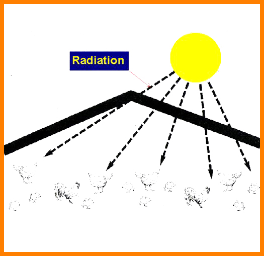
Radiation. Electromagnetic transfer of heat between masses at different temperatures.
Conduction. Transfer of heat through a solid medium.
Convection. Transfer of heat through the medium of a fluid; typically air.
All three of these heat transfer mechanisms are active to some degree in every application. Convection will be the dominant heat transfer mechanism in most applications. Nondominant effects will provide an added contribution to cooling; in some cases, however, they may result in undesirable and unanticipated thermal interactions between components and subassemblies. All three of these mechanisms should be given consideration when developing a successful cooling strategy.
RADIATION
Radiant heat transfer occurs continuously between objects at different temperatures that are exposed to each other.
The net effect on the temperature of an individual part is dependent on a great many factors, including its temperature relative to other parts, relative part orientations, surface finishes and spacing. The difficulty in quantifying many of these factors, combined with the universal presence of radiant energy exchange, makes calculation of radiational temperature effects both a complex and generally imprecise task.
Temperature differentials encountered in practical applications of Vicor converters are never large enough to cause radiational cooling to be the dominant heat transfer mechanism. Radiation will account for less than 10% of total heat transfer in the majority of cases. For these reasons, the presence of radiant cooling is often assumed to provide safety margins over and above the dominant cooling mechanism, and detailed consideration of its effects are neglected. A valid assumption, in most cases, is that the converter will be warmer than its surroundings and radiant energy transfer will aid cooling.
In some cases, however, nearby objects (PC boards, power resistors, etc.) may be much hotter than the converter and net radiant energy transfer may actually increase the converter’s temperature.
Surveying the relative positions and estimated temperatures of converters and surrounding parts is advisable as a means of anticipating the potential effects of radiant transfer. In cases where hot components are in close proximity to the converter, the use of interposing barriers can generally moderate undesirable radiational heating effects.
CONDUCTION
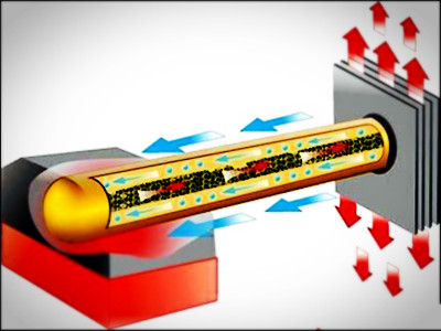
In most applications, heat will be conducted from the baseplate into an attached heat sink or heat conducting member. Heat conducted across the interface between the baseplate and mating member will result in a temperature drop which must be controlled. As shown in Figure 20–2, the interface can be modeled as a “thermal resistance” in series with the dissipated power flow. The baseplate temperature will be the sum of the temperature rise in the interface and the temperature of the member to which
the baseplate is attached.
Temperature rise across a surface interface can be significant if not controlled. The area of the interface should be as large as possible, and the surface flatness of the attached member should be within 5 mils. Thermal compound or a thermal pad should be used to fill surface irregularities. Thermal resistance across surface interfaces can be held to under 0.1˚C/Watt with proper measures.
Many applications require that heat be conducted from the baseplate of the converter to a “remote” dissipative surface via a thermally conductive member. The resulting baseplate temperature will be the sum of the temperature of the dissipative surface, the temperature rise in the heat conducting member, and the rises across the two surface interfaces. The thermal resistance of the conductive member is proportional to its length, and inversely proportional to both its cross-sectional area and thermal conductivity (Figure 20–3). Minimizing total temperature rise is dependent on controlling interface resistance, as described above, and controlling the thermal resistance of the transfer member through appropriate material selection and dimensioning.
CONVECTION
Convective heat transfer into air is a common method for cooling Vicor converters. “Free” or “natural” convection refers to heat transfer from a dissipative surface into a cooler surrounding mass of otherwise still air; forced convection refers to heat transfer into a moving air stream.
The convection cooling model is shown in Figure 20-4. Baseplate temperature depends on the temperature of the air, total dissipated power and the values of two thermal resistances; the thermal resistance of the surface interface between the baseplate and the heat sink, and the heat sink-to-air thermal resistance. Surface interface resistance can be minimized as discussed under Conduction. The heat sink-to-air resistance is dependent on a variety of factors including heat sink material and geometry, air temperature, air density and air flow rate. Fortunately, thermal resistance data is available for a very wide range of standard heat sinks for use in both free and forced convection applications. The following sections will provide guidelines for both free and forced convection cooling of Vicor converters and configurables.

 +86-755-89375091